|
Home theater systems are gaining in popularity every day. Unfortunately,
the need for five high-quality loudspeakers plus a subwoofer or two can
take the cost of these systems out of the price range of many who would
otherwise enjoy them. Our newly developed line of lower-cost fully
shielded drivers forms the basis for the Designer Series of home theater
loudspeaker system. Building on the foundation of this new driver line Joe
D'Appolito of Audio and Acoustics, Ltd. has designed a complete home
theater speaker system for us. The full specifications for the system,
including cabinet drawings, crossover schematics, parts lists and typical
performance curves are included in these pages.
The focus of
this kit design is our new PC (Polymer Chassis) series range of drivers.
Our R&D team has selected the highest grade of pure polymer for the basis
of this concept. Each chassis shape and profile was analyzed and dissected
by our CAD software to create the best ratio between the mechanical
properties, weight to stiffness, material flow and molding cycle time. The
end results are the PC drivers deliver increased efficiency due to the
non-magnetic properties of the polymer, improve the stray flux
cancellation and offer superior environmental strength.
In
addition, we offer 3 cone materials to choose from: Patented HD-A, Coated
Paper and Paper. We have selected our patented HD-A cone technology for
this kit project. Light, stiff and well damped make the HD-A cone a great
choice for the demands of the home theater market. In depth detail and
imaging allow you to enjoy the theater sound quality in your home.
HOME THEATER SYSTEM REQUIREMENTS
Home theater loudspeaker system requirements we are interested in fall
into three broad areas: Frequency response, polar response and maximum
sound pressure level (SPL). In discussing these requirements we must
differentiate between the two forms of home theater sound: the original
Dolby Pro Logic™ system and the newer Dolby Digital™ system also referred
to as AC-3 or 5.1 channel sound.
In both
systems the left, right and center channels cover the full audio frequency
range. The Pro Logic surround channel is monaural and limited in frequency
to a range of 100Hz to 7kHz. In Dolby Digital all channels are discrete
and full range. In addition to the front and surround channels a
low-frequency effects (LFE) channel is available for use with subwoofers.
Typically, the LFE channel handles frequencies from 20 to 80 Hz, although
the upper limit can be as high as 120Hz.
In addition
to frequency response, it is also important that all speakers in the
system match in the more subtle quality of timbre. All drivers in the
Audax home theater system use drivers from the same line and with the same
cone material, assuring spectral consistency across all channels.
The front
speakers in both systems contain strong directional queues. In Dolby
Digital the left and right surround channels also carry independent
directional information. Delayed sound arrivals due to reflections off the
walls, floor and ceiling can confuse these directional queues. Strong
reflections can also alter sonic timbres and make rapid sounds such as
speech syllables less clear. In addition to proper placement and room
treatment, limiting loudspeaker horizontal and vertical polar response can
greatly reduce these reflections and the undesirable effects they produce.
It is especially important to limit the vertical and horizontal coverage
of the front speakers, concentrating sound within the primary listening
and viewing area. Unfortunately we run into a conflict with the
requirements for good stereo sound reproduction where broader horizontal
coverage is desirable.
In the
Audax home theater system the MTM geometry is used in the left and right
speakers to limit and narrow vertical polar response. Proper selection of
driver size and crossover frequency controls horizontal coverage in all
front speakers. An appropriate compromise between stereo and home theater
coverage requirements has been made in the design of the left and right
speakers. Front speaker polar responses are described in later sections.
There is
disagreement on the most desirable polar response pattern for the surround
channels. The original THX (Tom Holman eXperiment) home theater
specification calls for a dipole pattern. This pattern is quite effective
with the monaural surround sound of Dolby Pro-Logic. The dipole produces a
"phasey" sound that is difficult to localize, adding to the surround
effect.
In AC-3 the
left and right surround channels are discrete and contain position
specific information. These surround channels will benefit greatly from
monopole speakers because they preserve the distinct directional queues
present in each AC-3 channel. This is true not only for home theater, but
also for the increasing number of music only recordings available in 5.1
channel sound. There is now a new THX specification for home theater
installations in smaller rooms, called THX Select. This specification
allows monopolar speakers for the surround channels. With proper placement
the monopole can be effective in both Dolby Pro-Logic and AC-3 surround
sound. (See section VIII.).
Realistic
reproduction of movie sound tracks can require short term SPLs of
105-110dB. All of the individual speakers in the Audax home theater system
can produce 105dB within their frequency range in typical size rooms.
Their combined output capability easily exceeds 110dB. Sensitivity for the
speakers in this system falls in the range of 87-88dB SPL/1w/1m. This
translates to minimum amplifier power requirements of 100 per channel.
THE AUDAX HOME THEATER SYSTEM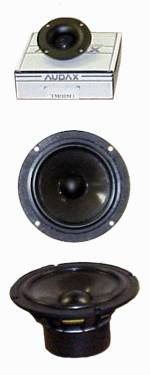
The complete Audax Home Theater Loudspeaker system is comprised of; front
left, right and center (LCR) speakers, left and right surround speakers
and a powered subwoofer. All speakers in the home theater system use
drivers from the same line, assuring spectral consistency across all
channels.
The left
and right channel speakers use the MTM geometry (the D'Appolito
configuration) with a pair of 6.5" mid-bass drivers flanking a soft dome
tweeter from the Audax Micro Series™ line. This compact tweeter permits
closer than normal spacing of the mid-bass drivers resulting in a near
ideal vertical polar response pattern for home theater application. The
left and right channel speakers are 2-way vented systems with a 4th order
acoustic in-phase crossover at 2650Hz. Sensitivity is rated at
88dB/2.83v/1m. Response is within +1.6dB from 100Hz to 20kHz. The low
frequency -3dB point is 50Hz. System impedance is 8W.
The center
channel speaker forms the heart of a home theater system. It defines the
focal point for all cinematic action. The center channel speaker must have
uniform horizontal polar response over the viewing region both to preserve
the spectral balance of spoken dialog and to center the action for
off-axis viewers. It should also be essentially a full range system.
To this
end, the center channel is a 3-way vented speaker. A Micro Series™ tweeter
and 5.25" mid-bass driver are vertically aligned and placed on the
centerline of the speaker baffle to handle the high frequencies and the
midrange. A pair of 6.5" woofers flanks the tweeter and midrange drivers.
Crossovers occur at 400Hz and 3.5kHz. On-axis frequency response is within
+1.6dB from 100Hz to 20kHz. The low frequency -3dB point is 55Hz and
sensitivity is 87.5dB/2.83v/1m. At typical viewing angles within +15o off
the on-axis position, response changes less than 1dB over the full
frequency range.
Aiming the
system toward AC-3, the monopole radiation pattern was chosen for the
surround speakers. The surround speaker uses the same 6.5" mid-bass driver
and tweeter used in the LCR channels. This surround speaker is a
closed-box 2-way design with a 4th order in-phase acoustic crossover at
3kHz. Response is within +1.5dB from 100Hz to 20kHz. The -3dB point is
85Hz and sensitivity is rated at 88dB/2.83v/1m.
The powered
subwoofer uses 12" long throw woofer in a vented enclosure to produce a
-3dB point of 30Hz. An integral 150-watt amplifier sums the left and right
channels to supply a mono signal to the woofer. There is a 12db/octave
electronic low-pass filter with a continuously variable crossover
frequency ranging from 40 to 200Hz. A direct input bypasses this crossover
to accept input from the LFE channel. A single subwoofer will produce
105dB SPL into a half-space at 26Hz. Corner placement and room gain can
add 6-10dB more to this figure.
CONSTRUCTION TIPS
Enclosure
Readymade enclosures are available from a list of suppliers presented
elsewhere in this brochure. For those of you who prefer to build the
enclosures, we generally recommend medium density fiberboard (MDF) or
particleboard for loudspeaker boxes. Both of these materials have
relatively high internal damping. The enclosures can be painted or
veneered to according to decorating needs. Furniture grade plywood (no
internal voids) can also be used, but may require additional bracing to
reduce cabinet wall vibrations. Minimum wall thickness should be ¾". 1" is
recommended for all front baffles and the subwoofer cabinet.
Cut all
panels to size and make all holes before assembly. Flush mount all drivers
to eliminate diffraction caused by the raised edge of the driver flange. A
router will be needed to rabbet driver flanges flush with the baffle. (The
TM025F1 micro tweeter does not require flush mounting.) Use weather
stripping available at hardware stores to seal the joint between driver
flanges and the speaker baffle. A tight seal is especially critical in
vented enclosures.
Butt joints
are shown on all enclosure drawings. This is the simplest joint and is
adequate for speaker box construction. Those among you with greater wood
working skills and the appropriate tools can certainly use more
sophisticated joints. Glue all joints with yellow carpenter's glue. Once
the glue is set, apply a silicone sealer or caulk to all inside seams and
joints, including terminal cups and ports, to seal the enclosure.
Grille
details are not included with the enclosure drawings. Grilles are not
recommended unless required for esthetic purposes or to protect drivers
from curious children or animals. The grilles supplied with most readymade
enclosures have bulky wooden frames that produce response irregularities
due to edge diffraction. These grilles are for cosmetic purposes only.
Wire frame grilles produce can be made that produce very little
diffraction. The wire frame is mounted to the front baffle with standoffs
and covered with an acoustically transparent cloth or reticulated open
cell foam. The grille supports the grille covering at its outer edges
only.
Crossover
Don't skimp on crossover components. High quality Mylar or metalized
polypropylene capacitors with at least a 100V rating should be used in all
crossovers. Air-core inductors are recommended for all coils except for
the woofer crossover coil in the center channel speaker. Because of its
large value, a high quality ferrite or iron core coil is specified here.
Wire size and resistance are specified for each coil. In general you
should avoid the urge to increase wire size for lower resistance. In most
cases, the coil resistance is critical to controlling crossover Q. Lower
resistance can lead to undesirable crossover response peaking.
Crossover
components should be firmly mounted to a ¼" Masonite™ or plywood board
with silicone glue or better still a product called "GOOP" available in
most hardware stores. High-pass and low-pass sections should be placed on
separate boards and placed opposite walls of the enclosure. You do not
need to be concerned about the effect of driver magnetic fields since all
woofers in this project are extremely well shielded. All resistors should
have at least a 10 watt power rating.
Suggested
component layouts for each crossover network are given in the text. You
may have to modify the suggested configuration to accommodate component
sizes or shapes that differ from those we used to develop the layouts.
THE LEFT & RIGHT CHANNEL SPEAKERS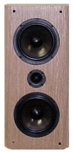
The left and right channel speakers are two-way MTM designs using a pair
of Audax AP170ZO 6.5" HD-A cone woofers and a TM025F1
textile dome tweeter from the Micro Series line. This tweeter employs a
high-energy neodymium magnet and a ferrofluid cooled voice coil for
increased power handling ability. The vented enclosure has been computer
optimized to maximize the power handling and low frequency extension of
the woofer pair. The result of this optimization is a low frequency -3dB
point of 50Hz with a 105db SPL capability at any frequency above the -3dB
point.
Crossover
The woofer and tweeter crossover have been computer optimized to provide
an overall fourth-order, in-phase acoustic crossover at 2650Hz. Driver
impedance and frequency response are fully accounted for in the
optimization process.
The
woofer crossover consists of a second-order low-pass filter realized
with L1 and C1 plus a controlled-Q parallel resonant trap made up of R1,
C2 and L2. The trap suppresses a peak in the woofer response at 3600Hz and
provides additional roll off of woofer frequency response above crossover.
The woofers are connected in series to better match the sensitivity of the
tweeter. Resistors R2 and R3 equalize power sharing between the two
woofers. 16-gauge wire is called out for L1. Although not necessary,
14-gauge wire may be used to gain a few tenths more dB in sensitivity.
The
tweeter crossover consists of a third-order electrical network made up
of C3, C4 and L3. L3 is made with 18-gauge wire. Do not use a larger wire
size. The resistance of the coil controls crossover Q. A larger size wire
will produce peaking of the tweeter response at crossover. Resistors R4
and R5 form an L-pad that attenuates tweeter response just enough to match
the sensitivity of the series woofer pair. Capacitor C5 rolls off a
high-frequency rise in tweeter response to produce an overall flat
response. Notice that all drivers are connected with positive polarity.
Crossover Parts List
 |
L1 = 1.8mH, 0.43 ohms, #16AWG
|
|
L2 = 0.15mH, 0.17 ohms, #18AWG
|
|
L3 = 0.27mH, 0.24
ohms, #18AWG
|
|
C1 = 8mfd
|
|
C2 = 13mfd
(12mfd & 1mfd in parallel)
|
|
C3 = 6.8mfd
|
|
C4 = 15mfd
|
|
C5 = 2mfd
|
|
R1 = 18 ohms, 10watts
|
|
R2, R3 = 10 ohms,
25watts
|
|
R4 = 5 ohms, 10watts
|
|
R5 = 15 ohms,
10watts |
Enclosure
Left/Right
Channel Enclosures (1 of 2)
The
enclosure has a net internal volume of 30 liters. A 3" ID port tube 5
1/4" long tunes the enclosure to 49Hz. The interior port opening is
supported by and 8" x 8" piece of 1" MDF. This piece forms a baffle that
linearizes port volume velocity at high SPLs and also serves to brace the
enclosure sides against vibration. The port baffle should fit snugly
between the enclosure sides and be glued in place. The enclosure sides can
be drawn tightly to the interior port baffle with coarse-thread deck
screws. Both ends of the port tube have a ½" quarter round applied with a
quarter rounding router bit to further smooth airflow at the port
openings.
The
enclosure is internally damped with 2" "egg-crate" acoustic foam
placed on the top, bottom, rear and one side of the enclosure. The foam
can be glued in place with rug cement available at hardware stores. If
acoustic foam is not available, egg-crate foam mattress pad is an
acceptable substitute.
THE CENTER CHANNEL SPEAKER
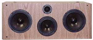
The center
channel speaker is designed to produce uniform frequency response over the
primary listening area. A Micro Series tweeter and AP130ZO 5.25"
HD-A coned mid-bass driver are vertically aligned and placed on the
centerline of the speaker baffle to handle the high frequencies and
midrange. A pair of 6.5" woofers flanks the tweeter and midrange drivers.
The woofer enclosure is vented and tuned to the same QB3 alignment used in
the left and right channel speakers. In typical listening rooms, the
center channel speaker can produce 105dB SPL at any frequency above 50Hz.
Center
channel on-axis frequency response is within +1.5dB from 100Hz to 20kHz.
The low frequency -3dB point is 50Hz and sensitivity is 87.5dB/2.83v/1m.
Crossovers are seen to occur at 400Hz and 3.5kHz. The response of the
woofer pair, midrange and tweeter are each down 6dB at their respective
crossover frequencies indicating that the drivers are in phase at
crossover.
Impedance
is above 7.5W throughout most of the low-frequency range. The minimum
impedance of 5W occurs at 4.5kHz. This is frequency is high enough to be
of little concern. Phase angle lies within +40o over the entire frequency
range. This is an easy load for typical multi-channel home theater
receivers.
Crossover
The low-pass filter comprised of L1 and C1 constitutes a second-order
electrical network. Similar to the L/R speaker, resistors R1 and R2
equalize power sharing between the two woofers. Notice that the woofers
are connected in reverse polarity as required for 2nd-order in-phase
crossovers. Because of its large value, an iron core or ferrite core coil
can be used for L1. The specified DCR for L1 is 0.48W. We have experienced
no undesirable effects on performance using the cored coil. The purest
among you can replace L1 with a 12-gauge air-core coil. Just remember that
this coil will weigh about 6 pounds and cost US $35-40 plus shipping!
The
midrange crossover has 2nd-order high-pass and 3rd-order low-pass
characteristics. The topology is a bit unusual in that it does not
resemble the traditional high-pass/low-pass cascade. Rather the topology
is derived from a low-pass to band pass transformation. You can think of
the 400Hz high-pass filter as being made up of L2, C3 and R5. This
combination provides a 2nd-order response to compliment the 2nd-order
woofer roll off. R5 controls the Q of the 2nd-order response. C2, L3 and
C7 make up a 3rd-order low-pass. This electrical filter combines with the
natural response of the midrange to produce an overall 4th-order in-phase
high-pass response at 3500Hz.
The tweeter
high-pass filter is also a 3rd-order electrical filter. Again, this filter
combines with the tweeter response to yield an overall 4th-order in-phase
response. The high-frequency roll off capacitor used in the L/R speaker
crossover (C5 of Fig. 7) is not needed here since the 3500Hz-crossover
frequency is above the point where the tweeter response begins to rise.
Crossover Parts List
|
L1 = 6.8mH, 0.48 ohms, ferrite or iron core (#12AWG air core for the purist)
|
|
L2 =
1.2mH, 0.34 ohms, #16AWG
|
|
L3 =
2.7mH, 0.53 ohms, #16AWG*
|
|
L4 =
0.27mH, 0.24 ohms, #18AWG
|
|
C1 = 62mfd
|
|
C2 =
24mfd
|
|
C3 =
10mfd
|
|
C4 =
82mfd
|
|
C5 =
4.7mfd
|
|
C6 =
8 mfd
|
|
R1, R2 = 10 ohms, 25watts
|
|
R3 =
8 ohms, 10watts
|
|
R4 =
15 ohms, 10watts
|
|
R5 =
2 ohms, 10watts |
Enclosure
The bass
response alignment is the same as that used in the L/R speakers. That is,
the internal volume of 30 liters occupied by the woofers is tuned to 49Hz.
However, the 3" ID port used in the L/R speakers is replaced with two 2"
ID ports 5" in length. The center channel enclosure contains a 6-liter sub
enclosure housing the 5.25" midrange driver and tweeter. The rear wall of
the sub enclosure is lined with 2" acoustic foam and filled with lightly
compressed hi-loft Dacron™ pillow stuffing. The woofer volume is damped
with 2" acoustic foam applied to the rear, sides and top or bottom (not
both) of the enclosure.
THE SURROUND SPEAKER
The surround speaker is a closed-box design using the same 6.5" woofer
and Micro Tweeter used in the L/R and center channel speakers. Response is
flat within +1.6dB from 100Hz to 20kHz. The half-space -3dB point is at
85Hz. Bass response will extend below this frequency when the surround
speaker is placed against a wall. Sensitivity averages 88db/2.83v/1m. A
4th-order acoustic crossover occurs at 3kHz.
The woofer
crossover network is 2nd-order electrical, but it combines with the
natural roll off of the woofer to produce and overall 4th-order acoustic
response. The tweeter also achieves a 4th-order characteristic with a
2nd-order electrical filter. Crossover component values are given in Table
3. All coils are air-core.
Crossover
Parts List
| L1 =
1.5mH, 0.4 ohms, #16AWG air core |
|
L2 =
0.22mH, 0.2 ohms, #18AWG
|
|
C1 =
11mfd (10mfd & 1 mfd in parallel)
|
|
C2 =
8mfd
|
|
R1 =
5 ohms, 10 watts
|
|
R2 =
15 ohms, 10 watts |
THE POWERED SUBWOOFER
The subwoofer uses an Audax HT300Z2 long-throw 12" woofer in a vented
enclosure. An extended bass shelf alignment was selected for maximum bass
extension. The net internal volume of 80 liters is tuned to 30Hz. The
subwoofer's half-space -3dB frequency is 30Hz. A single subwoofer will
produce 105dB SPL into a half-space at 30Hz. Corner placement and room
gain can add 6-10dB more to this figure and extend useful output below
25Hz.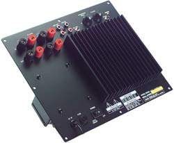
The
subwoofer is powered with an integral 150-watt amplifier. This amplifier
sums the left and right channels to supply a mono signal to the 12"
woofer. There is a 12db/octave electronic low-pass filter with a
continuously variable crossover frequency ranging from 40 to 200Hz. A
direct input bypasses this crossover to accept a low frequency effects (LFE)
channel input.
Enclosure
The cabinet is a perfect cube. 1" MDF is used for all walls. 2" x 3"
internal bracing stiffens the walls. A 4" ID PVC pipe 7¾" long tunes the
enclosure to 30Hz. A 7" x 7" internal baffle attached to the side and
bottom of the enclosure supports the port tube at its interior opening.
Both ends of the port are contoured with a ½" quarter round. The woofer
amplifier is mounted in an 8" x 8" cutout on the rear. The size of this
cutout may change depending upon the amplifier that you choose. The rear,
sides, top and bottom of the enclosure are lined with 2" acoustic foam.
SYSTEM SETUP
Loudspeaker Placement
Room reflections and standing waves have a strong effect on frequency
response. We have already discussed how we have minimized the effect of
room reflections on the higher frequencies through control of loudspeaker
polar response. Frequency response below 300Hz or so where all of the
speakers are omni-directional is largely controlled by standing wave modes
in your room and by loudspeaker and listening position placement relative
to those modes.
The
smoothest low-frequency response is usually attained using the rule of
thirds. That rule states that the speakers and the listener be placed at
all one-third points of the room dimensions. For example, consider a
rectangular floor plan with front speakers placed along a narrow wall. If
the long wall has a length L feet, then the rule of thirds dictates that
the front speakers and listening position be placed at distances of L/3
and 2L/3 feet respectively, from the short wall. The L and R speakers
should also be placed 1/3 of the room width from each side wall.
For any
particular room fully realizing the rule of thirds may be impractical, but
it is often possible to use the rule along one dimension. A typical home
theater loudspeaker placement is shown in below.
The left,
center and right speakers are arranged on a circular arc focused on the
primary listening position. This insures that these speakers are all at
the same distance from this point. Left and right speaker response is
smoothest when placed at least 2-3 feet from any wall. Ideally, the
distances to the front and side walls should not be the same.
You can
expect to experiment with surround speaker placement. Start with the
surrounds placed on the side directly in line with the seating position
and slightly above ear height. With Dolby Digital try pointing the
speakers directly at the listening position. You may prefer to move the
surrounds somewhat behind the listening position.
With Pro
Logic, place the surrounds against the wall and try pointing them forward
so that you are listening to them well off axis. You may also try moving
the surrounds more toward the rear and/or pointing them toward the rear.
When pointed to the rear, reversing the surround speaker phase may help.
Correct placement with Pro Logic movies may require some experimentation.
Be creative!
In order to
maximize bass coupling into the room, the subwoofer is generally placed in
a corner. If that is not possible, place the subwoofer at the intersection
of the floor and one wall. Depending on subwoofer crossover frequency,
corner placement may overly excite a particular standing wave mode. This
can lead to excessive bass "boom" or one-note bass. In this case, try
sliding the subwoofer along one wall by a few feet until the bass response
is tamed.
The image
below gives a suggested speaker placement for the ever-problematic "L"
shaped room.
 |