Huge Ass Disclaimer
I do not claim to be an "audiophile" with golden ears. I have my own personal tastes for music and how I like it presented to me just like everyone else does. My preferences may not be the same as yours. I am not an engineer and do not claim to be one. Pretty much everything here is the result of many years of dabbling with DIY speaker building. Although I believe the data collected and its interpretation presented is correct and valid they may in fact be completely wrong. This project was done completely for hobby/entertainment purposes only - read MY entertainment. If you choose to try out any of the modifications you are doing so at your own risk, you will most likely void a warranty and will be on your own to replace anything damaged. Did you try something and love the result? That's awesome. Did you try something and hate it? Sorry, please re-read the part about me not being an engineer. Did you try something and damage your speakers, amp, fingers, dog, etc? Sorry but you are a big boy and should know better than to do stuff you read on the internet. Did you duplicate this and get completely different results? Drop me a note and tell me where I @#$*ed up. So that's out of the way here goes...
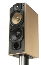
Grill Modification
While taking the initial measurements I noticed the grill itself was causing some minor roughness in the upper response. The Studio v3 uses a molded plastic grill wrapped in cloth. The curved shape of the grill gives it a classy appearance and has a side effect of forming a cavity close to the tweeter on both sides. This seems to be the main cause of the disturbance picked up by the mic. I must point out that this roughness is very slight and probably not audiable by most people. The easy fix is to roll up some felt and wedge it into the open cavity. Too much felt will cause a bulge on the front of the grill. I forgot to keep some snapshots of the tweeter response comparing with and without the felt. Next time the measuring tools are setup I may take some new measurements and post them. All the measurements shown on this page are with felt installed.
Initial Measurments
First task was to get some measurements and see what the response is like in stock trim. Measurements were taken indoors with the speaker on a higher than normal stand. Measurement distance was 113cm for far field and .5cm for near field. Both measurements were taken with my trusty Dayton microphone calibrated by Cross Spectrum Labs. All far field measurements were taken with the grill on and on the tweeter axis. Only a far field measurement was taken for the tweeter and a capacitor was placed in series to protect it. Once the measurements were spliced and tail corrected the minimum phase data was calculated and a computer model created.
First up is stock trim. The individual driver response curves shown are modeled with the stock crossover in place. The measured system response matched the modelled response very well so I didn't bother posting it.
- Stock Full Response on Axis
- Stock response vertically off axis +/- 15 degress
- Stock response horizontally off axis -15/-30 degrees
- Stock individual phase data
All this info suggests that I should have exported the images using a 40db scale instead of a 30db scale. The response looks much peakier then it really is. The keen observer may notice the tweeter and midrange curves meet closer to 2.5 khz than the spec'd 2 khz. This is due to the summation of the midrange and the woofer at the point of reference i.e.) the microphone position. Even at a normal listening distance there will still be some phase issues between the mid and woofer. The farther back you go integration improves but not it’s perfect and never will be. Besides some mild phasing issues on axis the off axis plots show additional information. Vertical off axis suggests these speakers will sound more even when the tweeter is placed above the listening axis and slightly toed in to each other. Depending on the room, 25 inch tall stands would put the tweeter above sitting ear level by several degrees or more and be enough to even out the mild peak in the 2.5-5kHz region. The transition from midrange to tweeter has a fair bit of overlap and I believe this is why some music sounds more forward and contributes to my listening fatigue. There are probably more factors Paradigm considered when designing the 40's but my guess is it came down to three; cost, placement by the average buyer and lastly the Studio models above 40's needed to sound a little extra refined for marketing purposes.
Crossover Modification 1
After some playing with some revised crossovers the following seemed to give the best response for least amount of changes. Most of the change occurs with the midrange circuit. The tweeter circuit is tweaked slightly to make the summation smoother and the woofer circuit wasn't touched at all. I generally don't like complex crossovers and the existing topology is already simple enough that works to tame the drivers where they need to be. My goal was to was bring the crossover slopes closer to 4th order and reduce the overlap between the midrange and tweeter. This revised low pass mostly eliminates the shelf between 2.2 - 2.8 kHz while using the stock topology and even fits on the stock PCB with the right sized components. This design gives a little more lift in the 200 to 400 Hz range giving a slightly "fuller" sound. When James Earl Jones is speaking he shouldn’t sound like Darth Vader taking a hit of helium.
The midrange inductor should have a DC resistance of .3 ohm to .5 ohm. This means a 1.15mh 18 gauge air core will work but its physical size will be tough to fit on the stock PCB. I used a steel laminate core I had in my parts bin. The value was a bit high so it was unwound by a few turns and the end result was 1.13 mh, close enough. Replacement resister is lynk metal oxide from Solen. A run of the mill ceramic wire wound would do the job just fine too. Make sure it’s a minimum of 10 watts. The capacitor is a decent quality non-polarized electrolytic. Going with a more expensive cap is a waste of money in this circuit. The stock tweeter circuit can be modified with a single 1uf cap put in parallel with the stock 5.6uf cap to bring it up to required value. Something like a 1uf Dayton cap will work nicely. Of course the tweeter circuit could be rebuilt with new values and this is the approach I choose. Again going overboard with a super capacitor is not a good value. A decent quality poly cap will do just fine. My thought is if the cost more than $8 per it’s a waste. This design has a much flatter response on axis and doesn't deviate as wildly when going off axis. I still prefer them placed so the listener is below tweeter axis. The "forward" sound quality is reduced and overall sounds much more balanced to my un-trained ears. ACDC at high volume no longer melts my face. I'm fairly picky on sibilance and can still hear some coming through unfortunately.
- Modded full response on axis
- Modded response vertically off axis +/- 15 degress
- Modded response horizontally off axis -15/-30 degree
- Modded individual phase data
- Modded transfer functions
- Low pass comparison - summation of midrange/woofer, compares stock response with modified response
- Modded crossover circuit - components circled in red are the new values
- PCB before modification - components circled are to be replaced
- PCB with midrange inductor and capacitor removed - the inductor is hot glued to PCB, care and some heat is needed to remove
Crossover Modification 2
This version was an attempt to correct the phase issues between the midrange and woofer. It still uses the same circuit topology for all drivers and keeps the overall response smooth. This option may work better when the speakers are placed farther from the wall and the tweeter is at listener height. I say "may" work better because I never listened to this version as my parts bin didn't have a large enough bar core inductor for the woofer circuit. When I find the right size coil I will definitely try it out. For time being this version is here just for comparison to the other options.
- Modded2 full response on axis
- Modded2 response vertically off axis 0/-10 degrees
- Modded2 crossover circuit
Tweeter Replacement
As luck would have it I have a pair of brand new old stock Vifa D27-TG-05-06 on hand. These are still made in Denmark before they moved manufacturing to China and went to crap. They have a reputation for being a good sounding solid tweeter. The stock tweeter seems to share a common design with Vifa D27 and they look close enough on the outside to be a drop in replacement. Hmmm..
Removing the face plate from the stock Paradigm tweeter reveals a magnet and diaphragm which is almost indistinguishable from the Vifa. The aluminum dome of the Paradigm is slightly shorter than the textile domed Vifa but the coil diameter is identical. A Vifa diaphragm will fit right in to the Paradigm magnet without issue and vice versa. Also the face plates between the Paradigm and Vifa are interchangeable with regards to fitting properly over the dome and having the same bolt pattern. There are however 2 problems with bolting a Vifa D27 tweeter to the stock Paradigm plate. First problem is the Vifa face plate is made to space the dome assembly 6mm below the surface and changing this spacing could have very negative consequences on response. Second problem is the Vifa has a taller dome and it hits the metal guard on the Paradigm plate designed to protect the dome.
I didn’t want to hack apart my stock face plates and managed to pick up a pair of damaged tweeters from a pair of Studio 100 v4's. To make the Vifa bolt up nicely I used a dremel to remove the guard and made some custom spacers out of styrene plastic. This spacer was kind of a pain to make. The face plate is designed to press down on the diaphragm evenly around the dome and line up with the 3 raised tabs on the magnet. When the face plate is bolted tight it can only put so much pressure on the diaphragm before coming to rest on the raised tabs keeping the pressure uniform. I picked up some styrene plastic sheet from a hobby shop in 2mm, .020" and .010" thickness. After building a few test spacers and doing some careful measurements the end product is a spacer which allows a D27 to bolt up squarely to the Paradigm face plate and recesses the tweeter almost 5mm. The metal lip on the Paradigm plate is just over 1mm thick giving nearly the same recess as a stock D27.
- Spacer front view
- Spacer back view
- Spacer front profile - The front side goes against the tweeter mounting plate. You can see a .020" plastic ring designed to pres against the outside edge of the dome opening.
- Spacer back profile - The back sits on top of the diaphram assembly. There is a .010" ring designed to keep the pressure consistent around the dome. This mimics how the stock D27 plate fits holds the diaphram in place.
- Spacer mounting tab profile - The spacer ears have 2 layers of plastic added. A .020" and .010" laminated together. When the spacer is placed on top of the diaphram assembly there is a small gap between the ears and the metal bolting tabs on the magnet assembly. When the front plate is placed on top of the spacer and bolted down this gap is closed and the front plate will rest evenly on all three ears. This keeps the front plate straight and even while putting enough pressure on the diaphram to keep it from moving around.
Now the D27 fits into the studio 40 cabinet it’s time for some measuring. This set of measurements were done on different days and it’s hard to get everything in the exact same position so there is a tiny bit of variation between these and the measurements taken with the stock tweeter. The Vifa is a bit more sensitive and required additional padding. You will notice the circuit is similar to the stock layout however the resister is placed before the inductor. I tried a couple other circuits and this one had the best combination of simplicity and sound quality. I used a Dayton 5.6uf poly cap and a mil spec resister from Solen. The resister (R1) can be tuned to personal taste, increasing it to 4.7ohm makes the response almost ruler flat for most of the tweeters range. I like the balance with the 3.6ohm in place so far. I may try a 4.3ohm down the road just to see if I can hear the difference. Most of the time I have preferred the sound of a cloth dome to a metal dome (ok the Bryston Mini T's sound awesome) and to my ears the D27 is the winner for the Studio 40's.
- All drivers unfiltered response
- System on axis response with crossover
- System vertical off axis response +/-15 degrees
- System horizontal off axis response -15/-30 degrees
- Individual phase response
- Crossover for Vifa D27
Once I'm sure this will be the final design I want to use some filler where the guard was attached and give the whole thing a fresh coat of black Krylon. For now the grill hides the ugly so I'm happy.
I was able to get some large value inductors and decided to try out crossover option #2. This version is almost a full baffle step desgin coming in at 5db of compensation. After some listening and tweaking these are the final results for the Vifa D27..
- New circuit with Vifa D27
- Actual measurement on axis at 1.15m
- Actual measurement on axis individual drivers
- Actual measurement on axis tweeter reverse polarity
- Simulated off axis simulation at 3m
- Simulated polar response at 3m
This updated circuit seems in increase the soundstage by a large margin making the speakers much less of a point source. My room is probably a bit small to be using a large 2.5way such as this and the updated circuit is allowing the drivers to integrate a little better in a shorter distance. The down side is the increased baffle step compensation in conjunction to their close placement to the back wall gives them a heavier or more chesty sound. I would really like to move them out a couple feet unfortunately its just not practical. Its a trade off I can deal with.
The stock tweeter should also benefit from the new lowpass circuits. Right now I'm still rockin the Vifa so I don't have a subjective review or actual measurements to go with it. All the info for the stock tweeter is from the computer model only. The nice part here is the complete stock Paradigm tweeter circuit can be used as is. If one wanted a perfectly flat response then a 1uf cap can be paralleled with the stock 5.6uf for a total of 6.6uf. Reality is it would take a really sensitive ear to pick up on the difference and leaving well enough alone would be just fine. For those with a pair of 40's and wanting to try out a new crossover this is the version to try first.
- New circuit with stock tweeter
- Simulated summation on axis at 1.15m
- Simulated off axis simulation at 3m
- Simulated polar response at 3m
Until next time.
lord_darkhelmet at accesscomm dot ca
site meter traffic