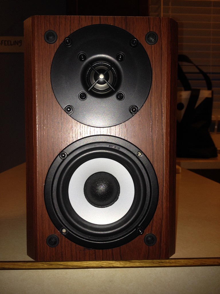
The stock tweeter is just a bit smaller than most dome tweeters available to the DIY'er. The few tweeters with the correct flange size were far to expensive to consider for this project. The only tweeter which fit perfectly and is cheap enough to make it worthwhile is the Dayton DC25T-8. At $12 per driver it was possible to swap both tweeters for half the cost of an original. As a bonus I have a pair of these on hand from speakers I built many years ago. The DHT is a well executed design from modest components and can be found here: Dayton Home Theater. My older gen tweeters were used to create the updated design and shown in the measuremnets on this page, hopefully the Dayton tweeter hasn't been changed over the years...
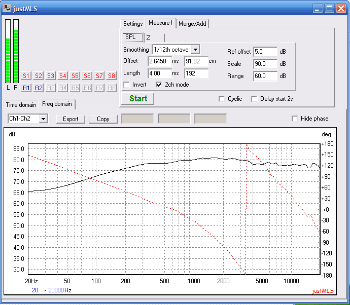
Problem of course is the stock crossover is guaranteed to not work with the Dayton tweeter and I never even bothered to try. I did measure the working M1 to get an idea of how they are designed. Below is the stock crossover schematic and the response taken at 90cm just off axis. Clearly there was effort put into the design to give them a pleasing sound with vocals. The bump from 2khz to 3khz will flatten out if you are listening slightly off axis.
The goal of this was to make the speakers functional for the lowest amount of dollars so I came up with a design having 2 options.
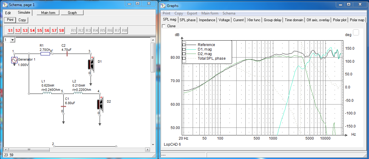
The beauty of the modded crossover is it makes use of all the original crossover components and the PCB. The only additional parts needed was a single 2.5uf cap and a 10ohm resister. One trace on the PCB was cut to convert the tweeter circuit into 3rd order electrical. A jumper was used to change the woofer circuit from 3rd order to 2nd order electrical. I didn't have time to take pics of it so I leave it to the reader to figure it out. After some modeling on the computer here is the resulting circuit and response. The 12.7ohm resistor is acutally the existing 2.7ohm resistor and an extra 10ohm resistor wired in series. This circuit is the cheapest and repurposes all existing components. The trade off is it decreases the amount of baffle step compensation by about 1db and as a result the speakers will have a fuller sound when placed close to a wall. I was aiming for a crossover point closer to 3.3khz but it wasn't going to happen without replacing more parts.
For those who may have these on stands away from a wall will prefer to swap the .62mh coil in the lowpass for a .80mh and replace the 12.7ohm resistor with a 15ohm. This will flatten the response out closer to stock but adds the cost of a new inductor coil and the larger coil may not fit so great on the stock PCB. Since these were going to be used as surround speakers near a wall I stuck with the .62mh coil and 12.7ohm resistor.
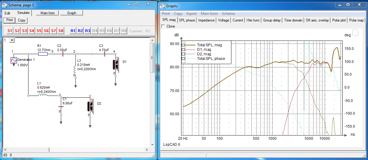
After the new tweeters arrived I was sad to see the design had changed a little bit. The terminals are now spaced further out from the magnet assembly and required the tweeter cutout to be notched in two spots to make room. Five minutes on each cabinet with a dremel notched the cutout but the fact they are not identical to my older gen units was not a good sign. Turns out there is a small change in efficiency but nothing serious, the large breakup node past 10k is pretty much gone. No more changes were made to the crossover. Here is the final result taken at 90cm.