Quatro 12 Subwoofer

Project Overview
This page details the build of my Quatro 12 powered subwoofer. The purpose of building this project was simply an experiment to see if I could get it to work.
Over the years I have dabbled with building my own subwoofers, but each design fell short of what I was hoping for in the end. Although for the most part they sounded quite decent, the failing point was how easy they were to bottom out or just did not produce the output I was hoping for. The Dayton DVC 12 sealed units were about the best sounding overall. They performed great with music and to an extent HT. They never produced the really really low stuff I like with movies and I had to be careful with the volume knob as they were easy to bottom out.
This time around I wanted to try something that isn't done very often. On message boards and box design software its often said to avoid using any type of boost with a ported design. The logic is the boost adds to the driver excursion and is likely to push it too far and result in physical damage. This seems reasonable and you can see it when its modeled with software. I wanted to see what would happen when a significant amount of boost is given precisely where driver excursion is at its absolute lowest - right at the tuning frequency. I played with some simulations and noticed if the boost was applied with precision it not only produced some really low bass but really had little affect on driver excursion. The other half of this project was to use a known alignment type and then validate the accuracy of the build using the methodology presented in The Loudspeaker Design Cookbook and Testing Loudspeakers.
Parts
Finding a driver suitable for my goal was not an easy task. My chosen alignment was an SBB4 and since I was going to apply some copious boost, I wanted the driver FS to fall in the mid to upper 20's. I was going to use a 5" diameter port to minimize port compression, since boost would be applied at tuning frequency the port would be moving more air than a non-boosted sub. So in the end I needed a driver with a suitable FS, capable of working in an SBB4 and require a box size large enough to fit the port !
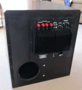
Most drivers I looked at required an odd box size or had too low of an Fs for my project. The drivers that did meet my criteria were pricey or hard to get. Since it was possible the whole project could literally blow up in my face, spending large dollars was not going to happen. When I saw the Quatro 12 on sale for $65 I gave its published numbers a quick once over with box software. It was not exactly was I needed - the Q value was a bit high and would have an effect on the rest of the design. In the end it came to be a balance of bass vs cost. For the amplifier; cost was a high priority but I also needed something with a tweakable boost circuit. My first choice was the BASH300 but it was out of stock at PE and the BASH500 was too expensive. The Dayton SA240 was on sale for $99 and it had the features I wanted so in the cart it went.
As of writing this, the Quatro 12 has been discontinued. Guess I know why it was on sale. I will continue to look for a suitable replacement and update the design in the future.
Enclosure
First order of business was to break in the driver a little bit. After 8 hours playing a 20hz sine wave I used Limp to measure the T/S specs. My specs came remarkably close to the published PE specs. I repeated the measurements to ensure I got the the numbers correct. My design used these specs to compute the box design:
Fs = 26.66 Hz
Re = 3.50 ohms[dc]
Le = 5181.01 uH
L2 = 2902.12 uH
R2 = 51.74 ohms
Qt = 0.35
Qes = 0.36
Qms = 12.10
Mms = 104.35 grams
Rms = 1.444985 kg/s
Cms = 0.000341 m/N
Vas = 115.54 liters
Sd= 490.87 cm^2
Bl = 13.095056 Tm
ETA = 0.59 %
Lp(2.83V/1m) = 93.41 dB
Closed Box Method:
Box volume = 61.50 liters
Diameter= 25.00 cm
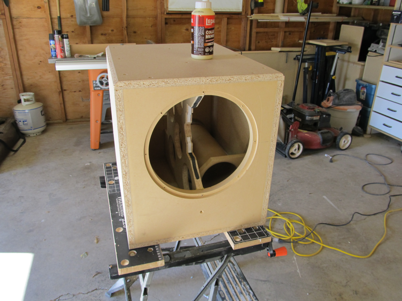
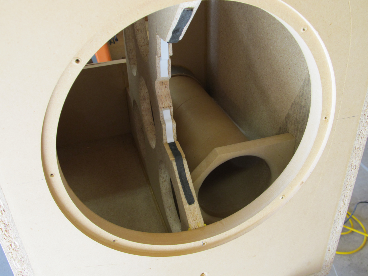
Under the assumption of a box loss value of 7 the volume required for the SBB4 alignment worked out to 2.21cuft net. After accounting for the volume displaced by the driver, port, amp and bracing the gross volume ended up at 2.65cuft. To give me some flexibility with box size I oversized it by a small margin and went with 2.8cuft gross then added .15cuft of compressed foam. Later on I discovered this was too small to achieve my SBB4. The software was calculating a port length of just over 20" for a 5" diameter port with tuning of 26.6hz. Adding dampening material to the box would increase the apparent volume and cause the port length to decrease. Not knowing this exact change in volume required impedance measurements to properly adjust the port length. I made a guess of 17" for a starting point and began taking measurements. My plan was to use the impedance sweeps to not only find the exact tuning but also work out the box losses and the box alpha. The box losses would give me my confirmation of accuracy, if I came close to 7 then the alpha should be close to the 1.84 as specified by the design charts and therefore the SBB4 would be achieved.
After fiddling with stuffing materials, port length and the compressed foam, I ended up at almost the exact tuning frequency of 26.6hz. The port was too long and and was cut to a total length of 16 1/8" (including a half inch round over used to make the flare). Impedance sweeps taken with and without stuffing show the tuning change from 28.4hz unstuffed to 26.7hz stuffed. My target box loss was 7 and I ended up at 5.71 with a box alpha of 1.34, this indicates that my box is undersized even after removing the .15cuft of compressed foam. This is a case of where the computer models don't always guarantee real world results. Rebuilding the box to 3cuft gross should bring the loss and alpha values to a near perfect SBB4. My options here were to either build a new box or try adding more stuffing. I didn't want to go through the tedious process of changing the port length by fractions of an inch again so I left well enough alone.
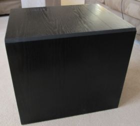
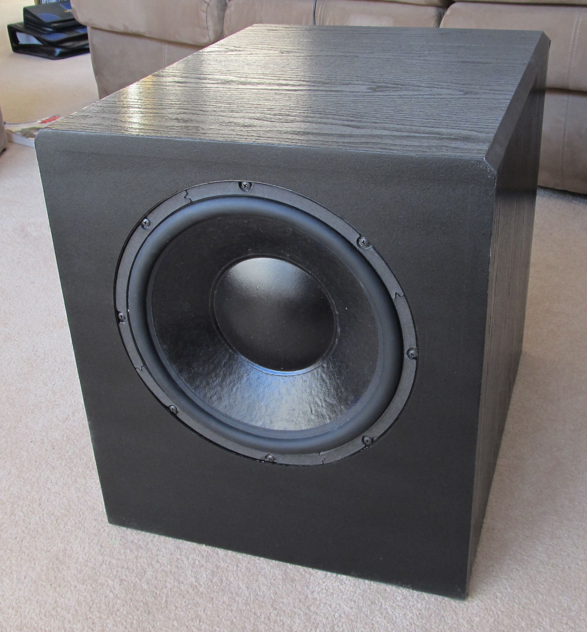
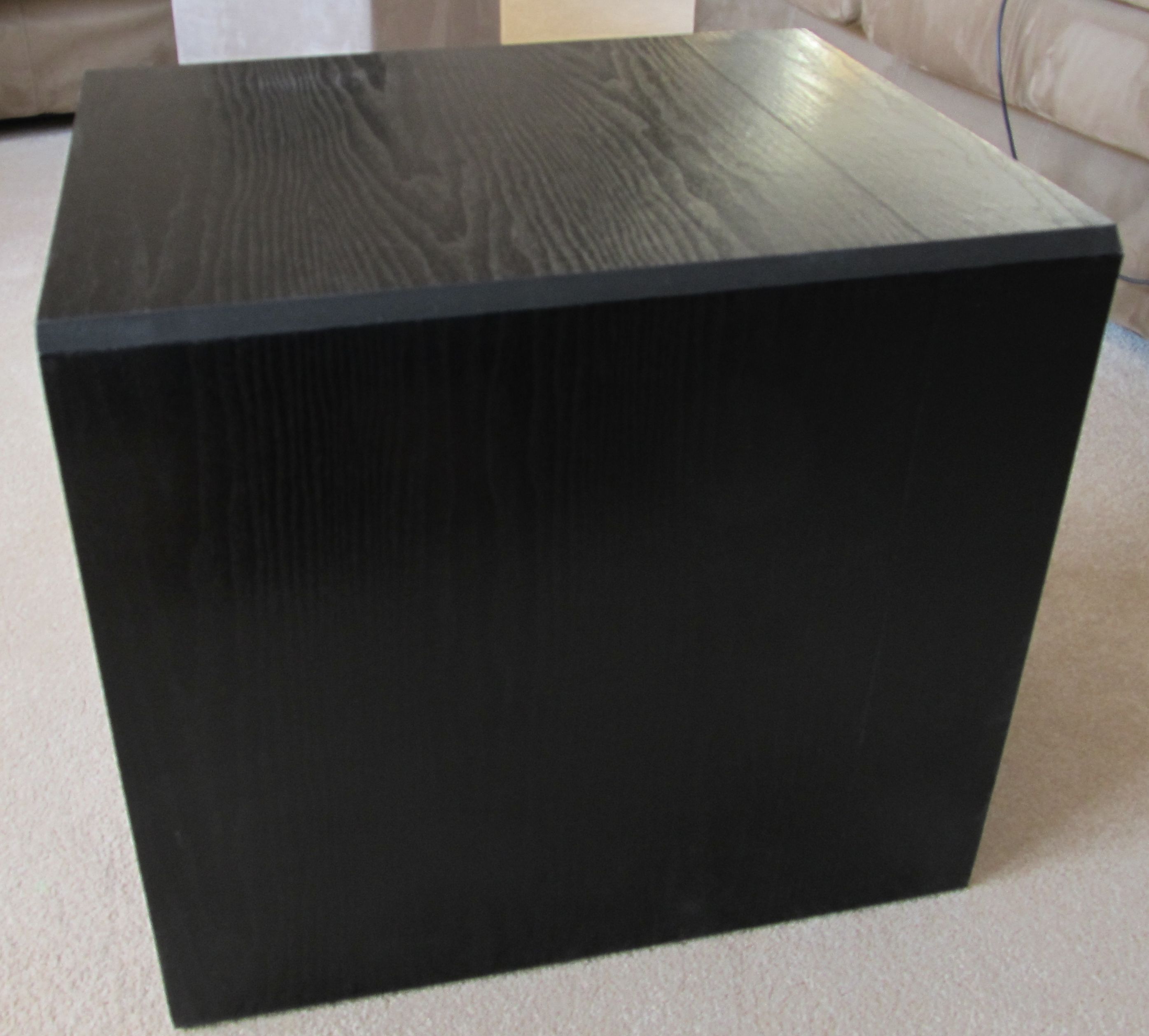
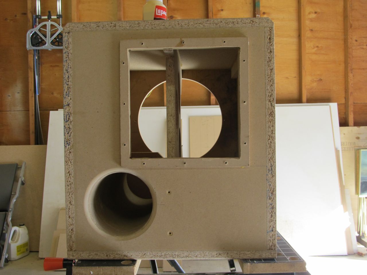
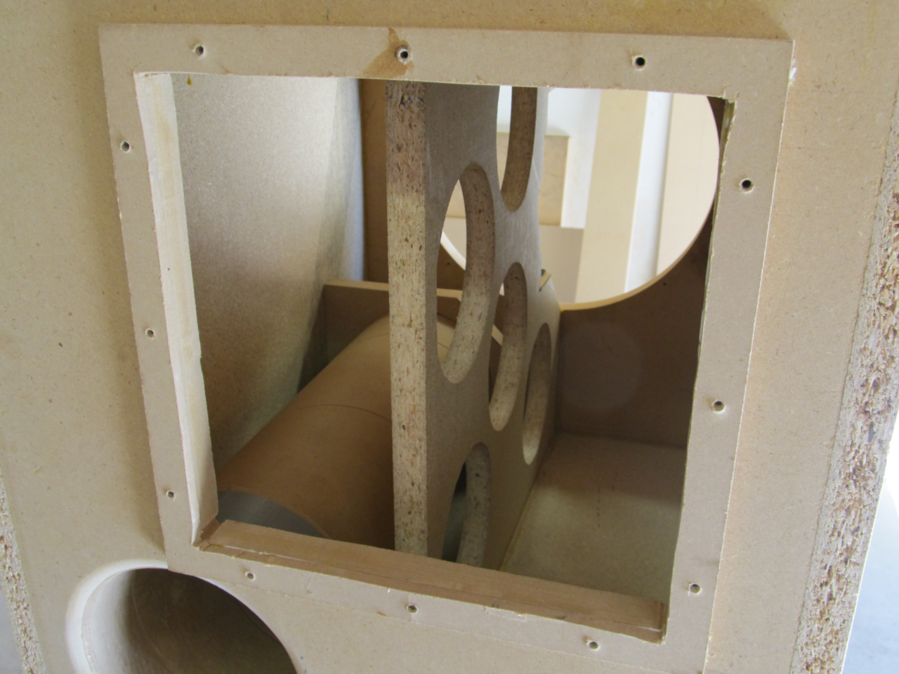
The box itself is nothing to write home about. I used 3/4" particle board for the sides, top and bottom. The front baffle is 1" mdf and the rear baffle is 3/4" mdf. There is a center brace running vertically supporting the magnet structure of the driver which ties the front & rear baffles together and to the top and bottom. The side panels have a vertical brace 1 1/2" wide running top to bottom at the mid point of the wall. Overall outside dimensions are 18 3/4 " tall by 16 1/2" wide and 20 3/4" deep. The port is mounted to give 1" clearance on the bottom and side panels. Stuffing material was some dense dacron-like material I found at a fabric shop.
Boost Circuit
Using a combination of Jeff Bagby's excellent "Woofer Box Model and Circuit Designer" and a trial license of LspCAD Lite; I worked out a EQ response curve which provides a boost of nearly 10db @ 26.6hz and a Q value of 1.33. The EQ curve was manipulated to begin providing some boost as the driver begins to roll off. Since the box was a bit small it caused the driver to roll off sooner then desired and I had to start appliying some boost at a higher frequency. The circuit went through too many alterations to describe in detail here. In the end the circuit design is based off of the Eight Band Sub-Woofer Graphic Equaliser by Rod Elliott over at ESP. My sequence of modeling, soldering and taking near field frequency measurements resulted in a 2 band EQ with 7db of boost @ 26.6hz and 2db of cut @ 62hz. Rod had written a handy little utility to calculate the resister values for the filter blocks based on your input criteria. You can find it on his project page. Many thanks to Rod for posting his projects which I'm sure many of us have learned from.
Putting it together
Since the EQ circuit was doing the majority of the work, the boost circuit on the amplier was disabled and set flat to 20hz. The EQ circuit provides some subsonic filtering and when its summed with the filter on the amplifier it does provide a fairly steep rolloff below 20hz. I am still tinkering with that a bit and may change the amplifier boost circuit to its standard no-boost setting and alter the EQ to compensate.
After hooking everything up and making sure it didn't catch fire. I began taking some near field frequency measuremnets to see how it ended up. As expected the higher Q value of the quatro 12 caused some peaking in the 80 to 90hz range. This peaking might increased further by the interaction of the EQ circuit and the amplifers internal crossovers. Whichever is the actual source of this, the upshot is the crossover knob on the amplifier is no longer accurate. As can be seen by the sweep taken with the amplifer crossover set to its maximum of 180hz, the peak looks unattractive to say the least and the -6db point is closer to 160hz, fig 5.
Most people would never have to cross a subwoofer that high, when used with more man-sized main speakers you get something closer to fig6. Here the crossover is set to roughly 90hz and the tick mark on the knob is pointing straight at the power indicator LED. Here the -6db point is closer to 105hz and the peak is eliminated. With my main speakers I find the best blend to be just below this setting, so about 90hz actual but the knob is set closer to 75hz.
Just to see the transfer function at work, fig7 is a sweep of the just amplifier with crossover set to 90hz and the EQ circuit.
Just to give a visual for how this all compares, fig8 shows an overlay of three nearfield graphs. The green curve is with the crossover set to 90hz, the blue curve is with crossover set to 180hz and the black curve is with crossover set to 180hz but the EQ circuit has been removed to show the effect.
I had wanted to take some measurements of the port output and then sum them in to get a complete picture but I ran out of time and had to pack up the measuring gear. Rest assurred the port adds some serious output !
Final thoughts
I've had it up and running for some time now and it still manages to impress me. For those seeking very musical and accurate bass they will need look elsewhere. While the boost does increase the output at low frequencies it also adds a fair amount of group delay, this is just the nature of the beast when dealing with filters and many may find it objectionable for critical listening. As for my muscial tastes it works quite well.
Going against the grain and rolling in a taylored EQ seems to have worked. Thus far I have never been able to run this creation out of power or make it bottom out. I have tried other ported designs going from just software sims alone and none of them were capable of producing this kind of output. In my previous house I had bass shakers in the sofa to give the tactile sensation everyone loves, this subwoofer provides the same level of impact without the shakers! End result is my previous dual DVC12s combined are no match for the sheer output and ample bottom end of the single Quatro.
If I was to do it over I would have waited for an amplifier with a variable phase control instead of a simple reverse switch. The lack of this feature makes the placement critical and I moved it around a fair bit until I was happy. I would have liked to hit my SBB4 target more precisely but that could be the NEXT big project.

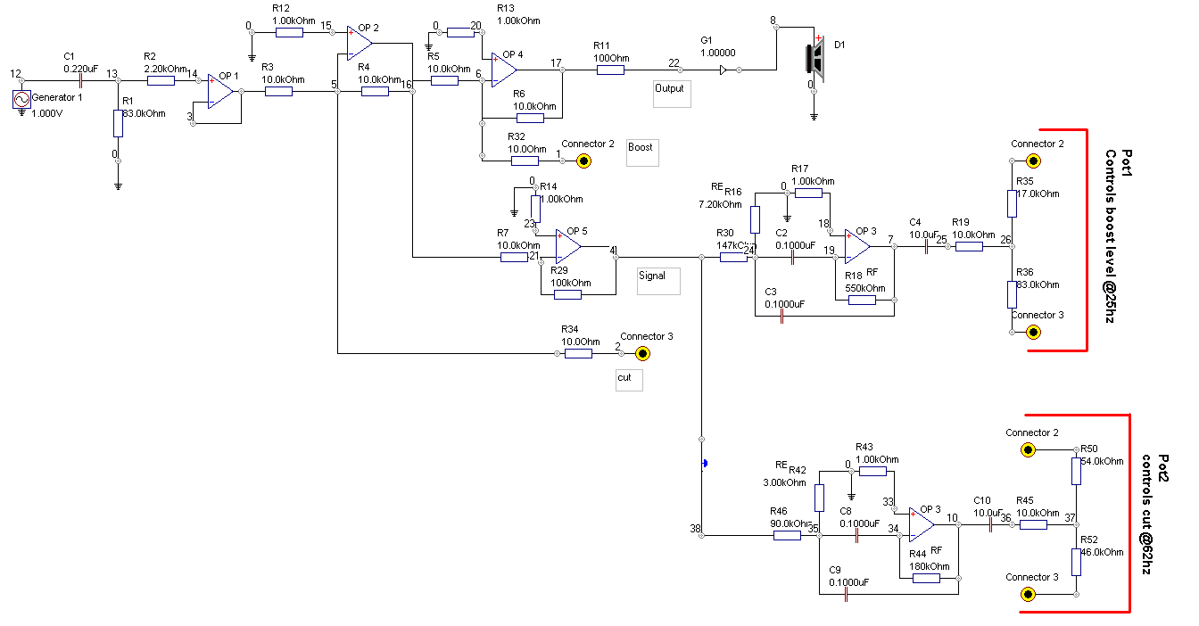 Boost Circuit
 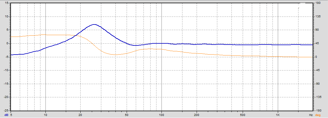 Measured response of EQ circuit
 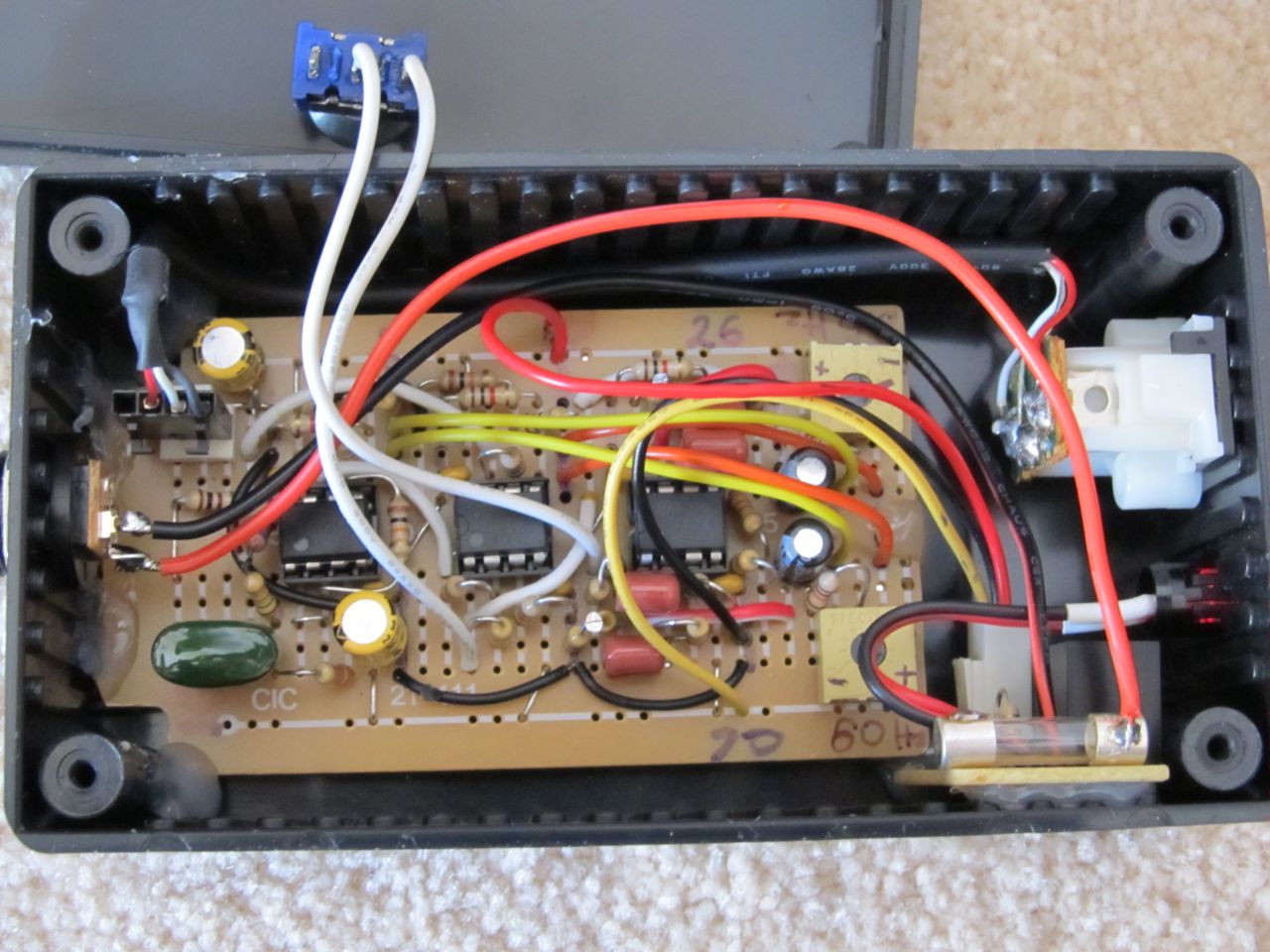 Completed EQ circuit
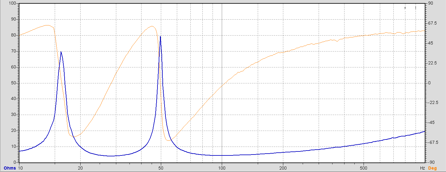 Impedance - Unstuffed
 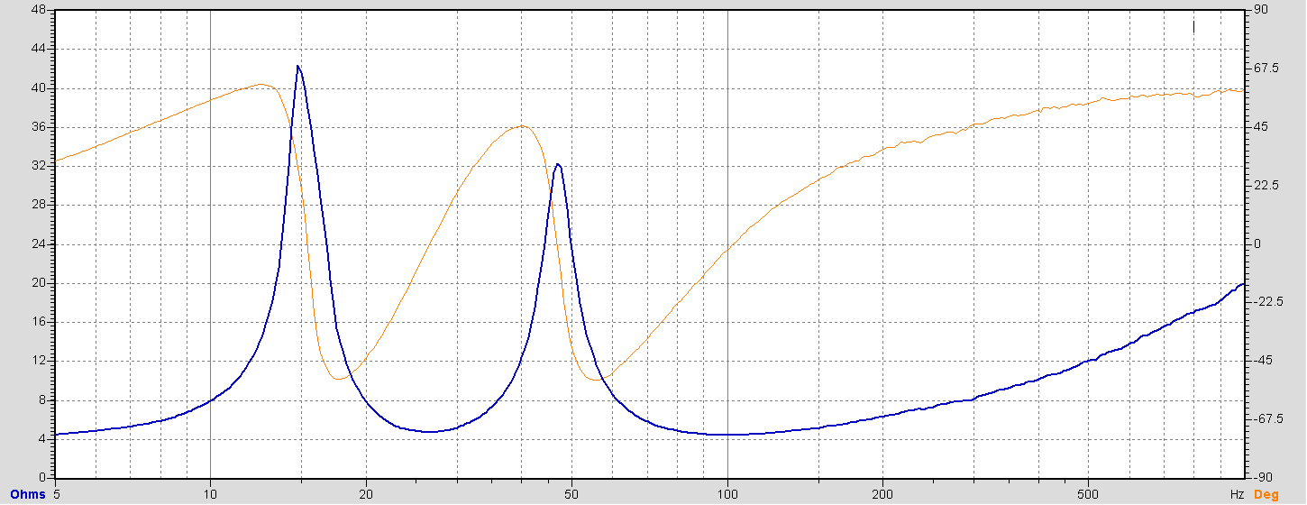 Impedance - Stuffed
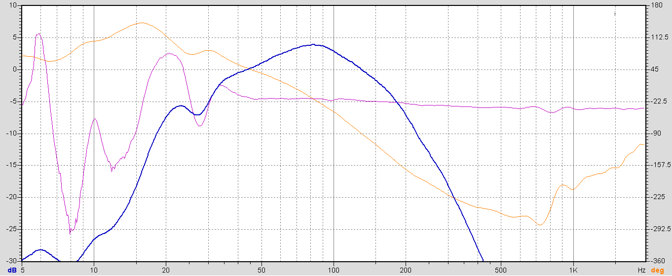 Fig 5. Nearfield crossover 180hz
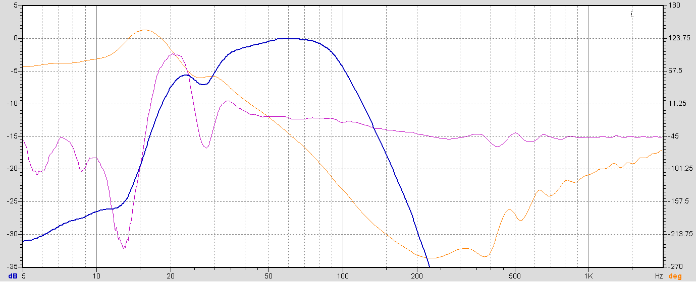 Fig6. Nearfield crossover 90hz
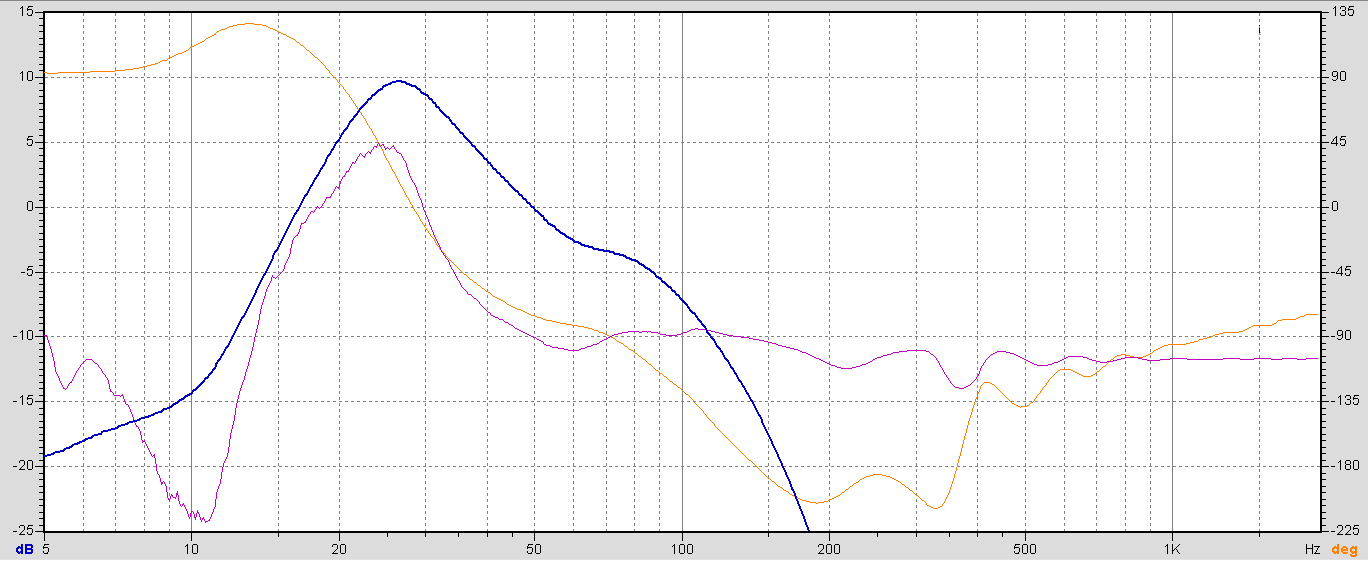 Fig7. Amp and EQ, set to 90hz
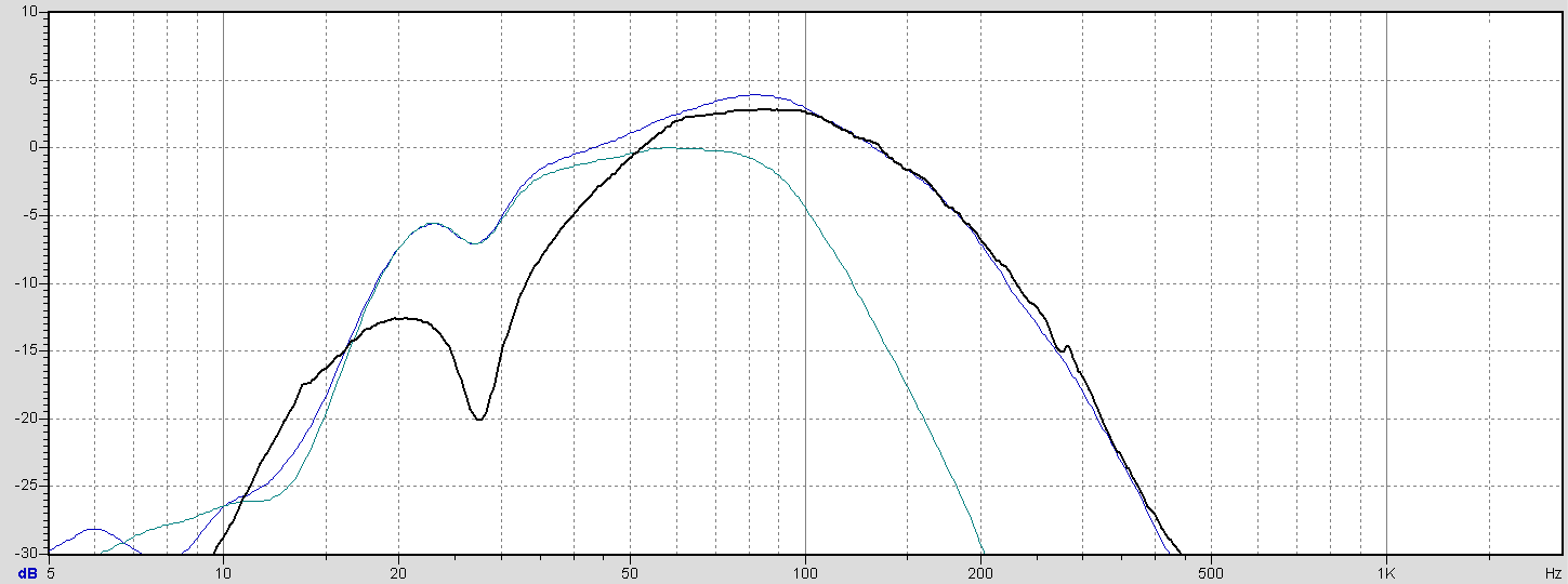 Fig8. Overlay of nearfield sweeps